IoT — Building an automated greenhouse Pt. I
Author
KalleDate Published

The course is coming slowly to an end, so it's time to bring all knowledge together and start building something useful. The goal is to have a little greenhouse to put on your window ledge, connected to sensors so you will get notified when it gets too hot/cold inside or the plants need new water.
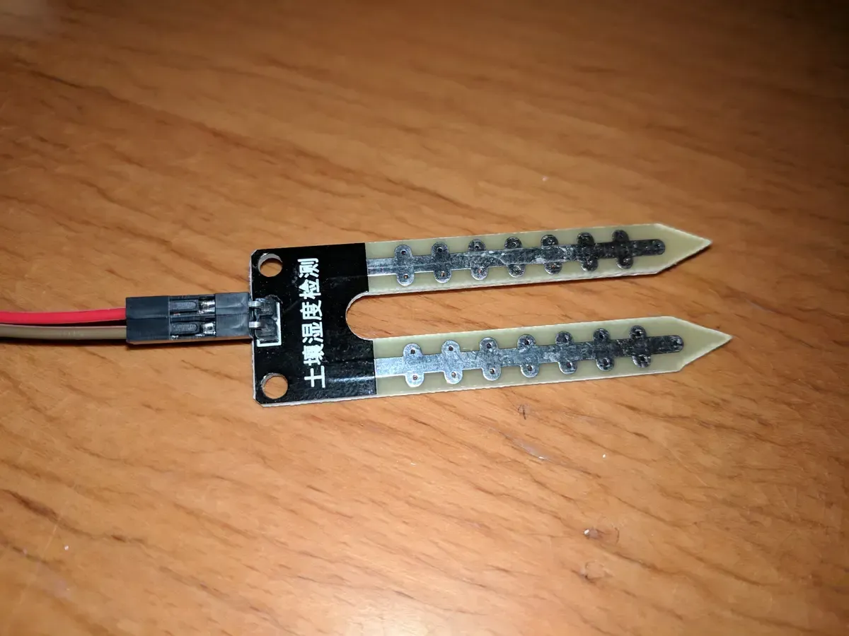
The Raspberry Pi and the program running on it already is capable of reading the temperature and humidity values which are both important environmental values to grow plants. But till now it's not possible to have any information about the soil and how much water is left. To measure the moisture of the soil there are simple sensors available, basically two metal pieces which are put in the ground to measure the electric conductivity.
Using this sensor brings another problem to the table, the Raspberry Pi doesn't have any analog-in pins. So to measure analog values you have to use an analog-digital-converter (ADC). In this Example I will use the MCP3008 chip which can be connected to the RasPi via the Serial Peripheral Interface (SPI) bus. SPI is deactivated by default so connect to your Raspberry Pi via ssh and run the raspi-config command with admin privileges:
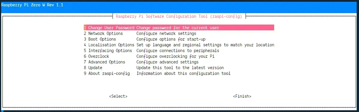
In the menu choose the Interfacing Options and activate SPI.
When SPI is enabled you can start wiring the MCP3008 chip to the Raspberry Pi. For orientation the chip has a small dent on one side. When aligned with the dent pointing to the left, the SPI connectors are on the top and the analog input pins are on the bottom.
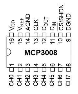
With the complete SPI bus connected you can use the other side of the MCP3008 to connect an analog input from a soil moisture sensor:

Now the only missing part is a little bit of software to collect the values and send them to the cloud. Like always with a node.js program the first step is choosing a library to make it as easy as possible to work with the SPI. This time the package of choice is mcp-spi-adc, start by running npm install mcp-spi-adc on the Raspberry Pi inside the directory of the firebase sensor project.
The following code snippet will read the analog input value on the pin 0 in an interval of 5 seconds:
Tasks
- activate the SPI bus on the Raspberry Pi
- connect the MCP3008 chip to the Raspberry Pi via SPI
- complete the wiring to connect a soil moisture sensor
- read the soil moisture values and store them in the firestore

IoT — Building an automated greenhouse Pt. II
Continue building an automated greenhouse by adding an interface to configure soil moisture reference values and implement authentication with Firebase. This guide explains protecting database access, setting up user authentication, and updating sensor data references in Firestore.
Mailing List
If you want to receive updates on new posts, leave your email below.